
Key Points Of This Chapter
The fluidized bed granulation and coating processes both involve the loading and unloading of materials. Since the core components and principles used in granulation and coating are different, in the process of loading and unloading, in addition to the most traditional In addition to manual operation, semi-automatic or automatic systems can also be added to complete loading and unloading, as detailed in this chapter.
During the feeding process of the fluidized bed with coating function, if it has a Wurster structure, the carrier material is often added manually or manually intervened to ensure that there is not too much accumulation in the guide tube and that the spray gun is not severely squeezed and blocked by the material. wait. In the unloading process, due to the use of different air flow distributors, there will be corresponding methods, such as flipping, tilting, etc.
For compounds with different activity levels, there are different considerations in the integrated system, such as: whether they are highly active substances, whether they are flammable and explosive, whether they are toxic and harmful, whether they are dust-explosive, etc. For the process, different functions are integrated. Ensure the safety, effectiveness and controllable quality of production.
This chapter also focuses on the handling of highly reactive substances.
Chapter 12 Integrated System
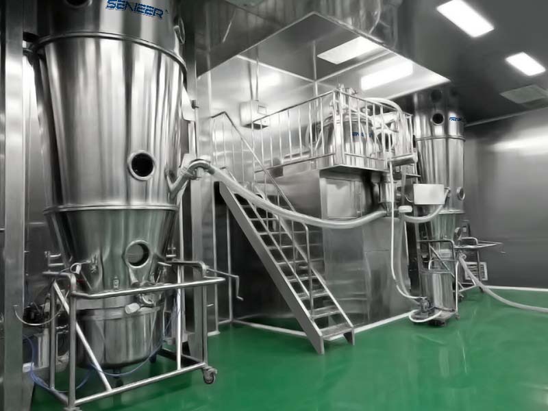
01 Material Handling
The flow of material into and out of the fluidized bed is an important consideration. As the process moves from development to pilot testing and into production, material handling becomes a major issue. Loading and unloading of the loading pot can be accomplished by manual, semi-automatic or integrated systems that transfer material to or from the fluidized bed depending on the process involved.
Manual Or Semi-Automatic Method
The traditional method of loading material is to remove the loading pot from the equipment, pour the material into it, and then push the loading pot back into the equipment. This loading method is simple and economical, but labor intensive. It has the potential to expose operators to dust and contaminate the work area. To avoid dust and cleaning hazards, a dust collection system should be installed to collect dust before it spreads. Hand loading also depends on batch size and the operator’s ability to handle the material. In addition, this method is time-consuming because some ingredients are added one by one during the granulation process. In addition to exposing operators to dust hazards, this method also has the potential for leakage, product loss, and impact on output.
Loading Material
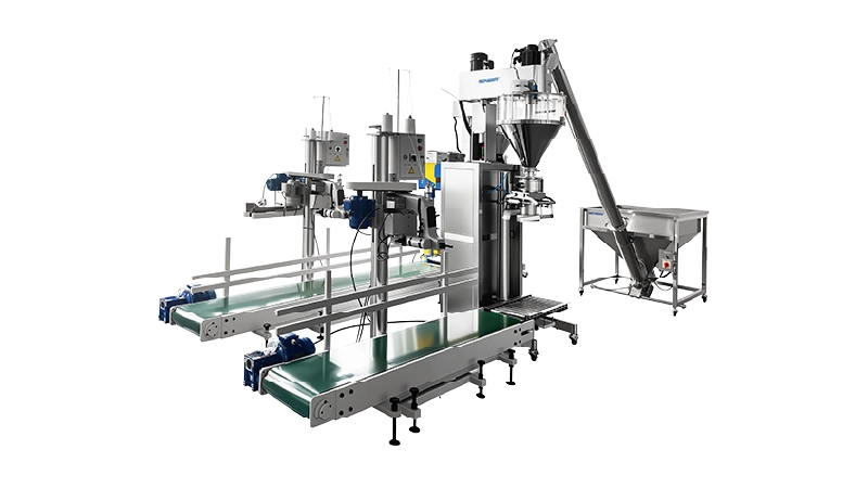
The loading process can be automated and isolated to avoid worker exposure, minimize dust generation, and reduce loading time. For the coating process, manual loading and unloading is the most common practice in the industry. There are two main types of loading systems in which the loading pot is kept in the processor: In the first system, the granulated raw material is added to the loading pot by gravity through an overhead material bucket (IBC), but this facility needs to be increased Ceiling height; Another system uses a fluidized bed to draw material from a transfer barrel or pre-weighed batching container. It is possible to draw material from the container because the operating fluidized bed acts like a negative pressure system. The fluidized bed is replenished by connecting the outlet of the IBC to one port of the fluidized bed. Once the material enters the fluidized bed, the product feed valve is closed and fluidization can continue. This transfer method uses a certain amount of fluidizing air to help the material pass through the transfer pipe. Loading can be done either from the top drum or from the floor drum. When materials are transferred vertically, less fluidizing air is required to pass through the transfer pipe because of the help of gravity, but vertical transfer requires a higher height to complete the material transfer. The advantages of this method of loading are limited operator contact time with the product, allowing the product to fluidize as it enters the handler, and reducing loading time. The disadvantage of this system is the need for cleaning between products.
Some varieties are suitable for granulation in High Shear Mixer rather than in fluidized beds. There are many reasons for this, such as low dose active pharmaceutical ingredient (API), low-level formulations of hydrophobic drugs that may need to be combined with large amounts of excipients, products with very low bulk density, poor flowability of the API and/or major excipients, requiring high bulk density Granulated products containing organic solvent binder solutions, etc. Most often, these varieties are granulated and then transferred to a fluidized bed for drying.
In most manufacturing plants, the High Shear Mixer is either in the same process chamber as the fluidized bed or is installed separately in another room. The granulated intermediate is transferred to a fluidized bed for drying. This requires manual handling from the discharge port of the high shear wet granulator to the loading kettle of the fluidized bed dryer. Wet materials from the High Shear Mixer are manually processed. The wet granular materials are discharged from the discharge trough. The discharge trough is placed at the discharge of the High Shear Mixer. The wet materials are collected and transferred to the flow stream. in the chemical bed processor.
As a more comprehensive approach, the main feedstock is vacuum-evacuated from a transfer barrel into a High Shear Mixer, and the effluent from the High Shear Mixer is transferred to a fluidized bed.
In most cases, fluid bed coating of pellets or granules requires nozzles to spray liquid from the bottom. When coating using a Wurster coating pan, the granules must be loaded carefully to avoid product entering the guide tube and covering the nozzle. In most cases, pellets are loaded manually.
Unloading
As with loading, the manual unloading method is to remove the loading pot from the unit. Once the loading pot is removed, the operator may scoop out the material from the loading pot. This is the most time-consuming and impractical method. Because operators may come into contact with the product. Alternatively, product can be vacuum transferred to a secondary container.
Another option is to install a tumbler, in which the mobile product containers of the fluidized bed processor are pushed under the loading pan-shaped tumbler and coupled together by an engaging switch lock. The container is then hydraulically lifted, rotated around the lifting column, and rotated 180 degrees for unloading. Using a pot tipping device or vacuum discharge device still requires the pot to be removed from the unit.
With the coating material being discharged, some fluid bed manufacturers have the ability to pneumatically tilt the lower distribution plate and collect the product into a container.
The loading pot remains in the fluidized bed processor, and there is a method for automatically unloading the product. The product can be unloaded from the bottom of the product container or from the side of the loading pot. There are two types of bottom discharge options, gravity or pneumatic. Gravity discharge allows the product to be collected into a container located beneath a lower plenum, possibly on a lower floor of a building. If overall ceiling height restrictions prevent gravity discharge, a gravity/pneumatic transfer combination may be considered. Gravity discharge can cause cleaning problems because process air and product discharge follow the same path; ensuring cleanliness is always a primary concern. The need to limit the machining area, and the development of air distributors in fish scale plate designs, prompted the consideration of side exhaust as an option. The loading pot is equipped with a discharge door.
Most of the granular materials flow freely and enter the container through the side discharge port. The remaining materials are discharged through the air distributor designed with fish scale plate by adjusting the air volume. If dry granulation is required, the discharged material can be pneumatically transported to the top bin. A closed system for unloading material helps isolate operators from the material. The isolation feature also prevents products from being exposed to contamination in the work environment. Material handling must be considered early in the equipment purchasing and facility planning process. Whether as an integral part of a High Shear Mixer/fluidized bed dryer or as an option in the granulation equipment, optimizing the process by considering these loading and unloading options can increase production efficiency and ultimately increase automation.
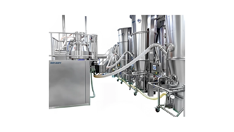
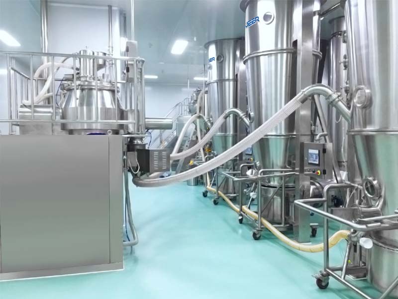
02 Integrated System For Non-Highly Active Compounds
For commercialized products, manual material transfer will be time-consuming and labor-intensive. For dedicated product setups, it is common to consider combining a fluidized bed drying operation with a High Shear Mixer, and equipping the High Shear Mixer with whole granules at its discharge. It is possible to run multiple high-volume products in an integrated system, but this will involve a lot of cleaning. The outlet of the High Shear Mixer is directly connected to the inlet of the fluidized bed dryer, eliminating the need for a long conveying pipeline. In this way, the material contact surface is minimized and throughput is increased. Even sticky granules that are difficult to convey by pneumatic force can be conveyed to the dryer easily and quickly.
If solvent-based formulations are produced in High Shear Mixers, special attention must be paid to explosion protection, and the integrated system can incorporate an integrated explosion protection concept. The various processing units of the High Shear Mixer and wet granulation can be protected with nitrogen during granulation. The dryer will be designed to resist 12bar pressure shock. The exhaust gas leaving the fluidized bed processor with the solvent vapor can be controlled in a manner that does not reach the lower explosion limit of the solvent. This will depend on how quickly the wet material carrying solvent is allowed to enter the fluidized bed processor. If solvent granulation is used, the waste gas must be passed through a catalytic oxidizer to burn off the solvent and then be discharged to the environment. Since the granulator and dryer are connected in a straight line, the explosion-proof valve usually required between the unit components can be omitted. This significantly reduces costs, setup time and maintenance.
The mixer granulator and fluidized bed dryer are mounted on the same frame and connected through an integrated operating platform. Peripheral components such as vacuum conveying systems for wet and dry granulation are integrated into the plant, allowing ergonomic inspection, maintenance and cleaning. Thanks to optimal ergonomics, the integrated system can be set up and operated by one operator if required.
Typical integrated systems in which containers are considered to control dust and cross-contamination. When the operations of these two units are consolidated into one unit, some points must be considered. Here are some factors that may need to be considered:
(1) Project layout, floor space, and ceiling height requirements.
(2) How to load the High Shear Mixer—loss-in-weight method, vacuum or manual?
(3) How to prepare the binder solution and add it to the high shear wet granulator? Is it a solvent, water or an organic solvent?
(4) How to determine and reproduce the granulation endpoint?
(5) How to complete the discharging of high shear wet granulator?
(6) Have the process parameters of granulation and fluidized bed drying been determined and are they repeatable, indicating that the process is stable?
(7) How will the material discharged from the fluidized bed dryer be treated? Does it need to be coated and remixed with lubricant?
(8) Is the system dedicated to a single product or multiple products?
(9) How will this system be cleaned?
(10) Is the control of a process completed by each unit individually or by an integrated control system?
03 Integrated Systems For Highly Active Compounds
In the case of less toxic drug substances, the primary driver for design is the possibility of preventing product contact with the free environment. For highly active APIs, the primary focus of design is to protect workers from harmful substances. This introduced the use of barrier technology, downward flow chambers, and other containment technologies. Innovative design solutions are needed to provide practical answers to sealing and cleaning problems.
APIs are becoming more and more toxic, and more than 50% of new chemical entities (NCEs) are classified as highly active [Occupational Exposure Limit (OEL) <10 μg/m3]. Additionally, health and safety authorities around the world are placing greater emphasis on the safety and protection of operators handling these substances. In response, suppliers of various hardware components have developed a variety of containment solutions, making it difficult even for the experienced person to determine which is best.
There is general consensus on the performance of a range of safety equipment, supported by occupational health monitoring. With the increased use of cleaning-in-place (CIP) systems in facilities, 1 μg/m3 facilities accept the trade-off of containment benefits and increased changeover downtime compared to 10-100 μg/m3 facilities. The true value of an integrated system is found in the granulation and drying of highly active compounds in a safe manner with minimal operator exposure. Based on an 8-hour time-weighted average, equipment can be designed to handle a wide range of APIs with OELs as low as 0.01μm/m3. The safe manufacturing of high-activity APIs and products containing these APIs requires both “hardware”—facility features, modern equipment, and engineering controls—and “software”—planning, practices, and procedures—to adequately protect people and the environment.
Three main factors determine how much containment is required and what containment methods are considered.
(1) Quantity, potency and toxicity level of raw materials
In most cases, the potency of a substance is characterized by the OEL or ADE (Acceptable Daily Exposure). ADE describes the absolute amount of a specific drug substance that can be absorbed by the operator without any negative health effects. The OEL describes the maximum concentration of pharmaceutical products that can be tolerated in the air of a production floor without any negative impact on the health of operators. For identified substances, these values are listed in several textbooks.
(2) Equipment and processes to be performed
Compared with 10-100 μg/m3, there are more dedicated facilities for 1μg/m3. The decision between multi-purpose and dedicated facilities is based on commercial or cleaning/GMP reasons rather than pure effectiveness. Companies use different criteria for risk assessment and have a consistent view of the factors considered.
(3) Working environment and operating activities of operators
Almost every company has its own classification system for determining the potency of ingredients to be processed, which does not take into account the dilution of the drug substance by excipients. Different companies have different guidelines and procedures for handling highly reactive compounds, depending on the facility, product and process. When considering fluid bed processing equipment options, equipment vendors, process teams, and safety experts should work together to select how highly reactive compounds should be manufactured and what engineering and operational controls should be implemented.
To address these factors, some general principles are listed below.
(1) Review and document potential health and safety hazards associated with the drug substance, including occupational health categories and explosive potential.
(2) Determine acceptable exposure levels and measure potential occupational exposure during the process.
(3) Implement appropriate containment and controls for hazards to reduce risks and verify the ability of containment to achieve safe and acceptable levels.
(4) Determine the potential impact of raw materials and related production processes on the environment.
(5) Where sealing is not feasible, use barriers and air purification to reduce the potential for material accumulation and exposure.
(6) Accelerate decisions on design strategies and containment requirements during technology transfer and introduction of new processes.
(7) Expedite decisions about design strategy and containment during the design of new facilities or renovation of existing operations.
(8) Implement appropriate levels of containment or infrastructure throughout the facility for compounds with comparable exposure levels or for the same compound to achieve maximum manufacturing flexibility.
(9) Implement permanent engineering controls to meet exposure criteria.
(10) Develop standard operating procedures and train processing, maintenance and QA/QC personnel.
(11) Plan maintenance needs.
(12) Conduct risk assessments to plan process failures and how to recover. Explore “what if” scenarios and documentation as a process.
(13) Provide backup in case of main container failure.
(14) Provide controlled flow paths for the movement of chemicals and equipment.
(15) Separate the personnel airlock and material airlock, and set up a disinfection shower in the personnel airlock.
(16) Document separators are included in effective kits as paper cannot be stained. Paperless technology should be evaluated.
(17) Continuously monitor environmental conditions such as relative humidity, temperature and pressure.
(18) Disposable air should be circulated 20 times per hour, and HEPA supply and return should be designed.
(19) Negative pressure in the processing area should be maintained.
(20) Bag-in/bag-out HEPA (BIBO) should be considered.
(21) Drain pipes need to be sealed.
(22) Personal protective equipment (PPE) is another expensive and complex element of high-containment production cells. Personal protective equipment is required only when isolation by engineered means is insufficient to protect workers from exposure above the composite OELs.
Material Handling Of Highly Reactive Compounds
Highly reactive compound handling requires special considerations, such as: securing raw materials, intermediates, and final products in and out of equipment ports; moving parts, tools, containers, samples, etc. into and out of enclosures; connecting critical utilities and/or liquid supplies or waste Drainage pipe; and adopt split reversing valve. Transfer systems are key to successful control. Cleaning, sampling and maintenance of the system must be considered during design.
A typical system containing high shear wet granulation and fluidized bed drying can be set up as follows:
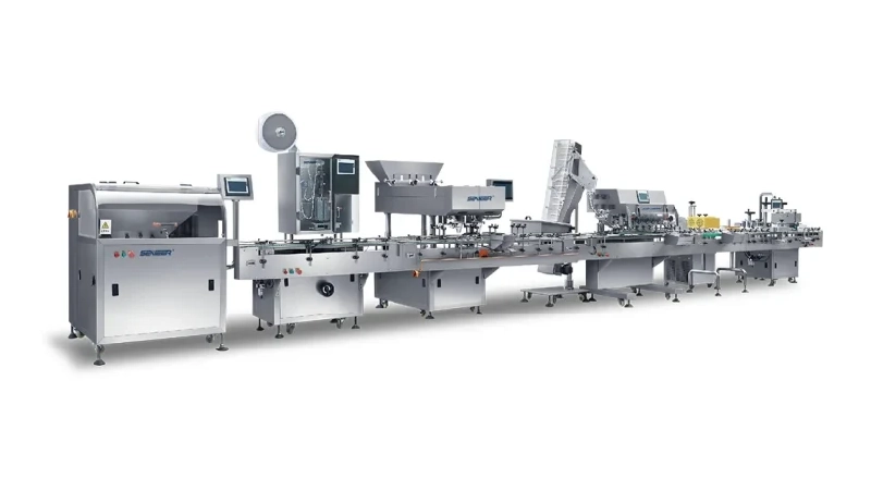
Granulation: Integrated production line, including high shear wet granulator, integrated wet granulation, wet material transfer line from High Shear Mixer to fluidized bed dryer, fluidized bed processor, integrated Vacuum transfer system for drying whole and dried granules from the fluidized bed processor to the IBC.
Material handling: IBC with sealing valves, vibrating feeders and mixing, disposable high-sealing interfaces such as Hicoflex, consisting of two complementary and self-closing half-couplings, tightly sealed and independent of each other, for isolation from The API is discharged from the device and charged into the High Shear Mixer, IBC material barrel, rear elevator, sealing valve of the tablet press, and IBC cleaning station.
Clean
Contamination/cross-contamination is a major issue during the manufacturing of solid dose products, especially in high-activity situations where very small amounts of compounds may produce therapeutic effects. Therefore, strict cleaning practices are necessary and cleanliness must be tested, possibly as low as single-digit ppm or “not detected” levels. The CIP system must be used to clean the fluidized bed and auxiliary equipment to handle high-activity compounds. CIP has several advantages:
(1) Fluidized bed processors with stainless steel filter elements and CIP will eliminate bag filter cleaning and operator exposure.
(2) Properly designed and verified, CIP reproduces the same working conditions and provides better cleaning assurance. It is important to remember that manual cleaning cannot be verified.
(3) The automated system does not require the presence of an operator and can be operated during off-duty hours, saving valuable processing time.
(4) There is no need to disassemble and reassemble equipment, thus shortening factory turnaround time.
(5) Separate employees from toxic or hazardous materials, including those used for cleaning.
(6) It is usually the most economical option because it reduces costs, cleaning time and uses cleaning chemicals more efficiently. It also reduces wastewater and its subsequent treatment.
(7) Some process materials cannot be easily cleaned by the solvent reflux method alone, but better results can be obtained by using detergents and cleaning agents.
04 Summary
The technology of high shear wet granulator combined with fluidized bed dryer is mature and has high output. Granulation processes using this method can compensate for fluctuations in raw material specifications and offer the possibility of integrating other unit operations.
However, there are some limitations, such as throughput loss, the system requiring a larger floor space, higher ceiling heights, and lengthy cleaning and changeover times for multiple product applications. However, a verifiable CIP can aid cleanup efforts.
If a new facility is to be built with an integrated system to handle highly reactive compounds, a team of experts from processing, engineering, occupational health, maintenance, quality, safety and industrial hygiene and equipment suppliers must meet and come up with a Action plan to address safe, high-quality production of highly active compounds to optimize processes.